
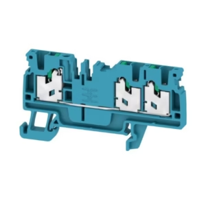
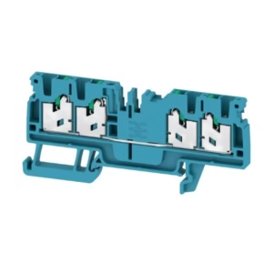
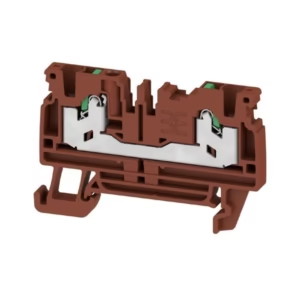
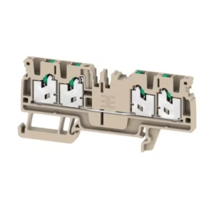
Printed circuit board terminals, 5.08 mm, Number of poles: 11, 180°, Solder pin length (l): 3.2 mm, tinned, orange, Clamping yoke connection, Clamping range, max. : 6 mm², Box
Technical Specifications:
| Depth | 17.1 mm |
| Depth (inches) | 0.673 inch |
| Height | 14.2 mm |
| Height (inches) | 0.559 inch |
| Height of lowest version | 11 mm |
| Width | 56.53 mm |
| Width (inches) | 2.226 inch |
| Net weight | 15.895 g |
| RoHS Compliance Status | Compliant without exemption |
| REACH SVHC | No SVHC above 0.1 wt% |
| Product family | OMNIMATE Signal – series LL |
| Wire connection method | Clamping yoke connection |
| Property, clamping point | WireReady |
| Mounting onto the PCB | THT solder connection |
| Conductor outlet direction | 180° |
| Pitch in mm (P) | 5.08 mm |
| Pitch in inches (P) | 0.2 “ |
| Number of poles | 11 |
| Pin series quantity | 1 |
| Fitted by customer | Yes |
| Number of rows | 1 |
| Max. adjacent poles per row | 24 |
| Solder pin length (l) | 3.2 mm |
| Solder pin dimensions | 0.75 x 0.9 mm |
| Solder eyelet hole diameter (D) | 1.3 mm |
| Solder eyelet hole diameter tolerance (D) | + 0,1 mm |
| Number of solder pins per pole | 1 |
| Screwdriver blade | 0.6 x 3.5 |
| Screwdriver blade standard | DIN 5264 |
| Tightening torque, min. | 0.5 Nm |
| Tightening torque, max. | 0.6 Nm |
| Clamping screw | M 3 |
| Stripping length | 6 mm |
| L1 in mm | 50.8 mm |
| L1 in inches | 2 “ |
| Touch-safe protection acc. to DIN VDE 0470 | IP 20 |
| Touch-safe protection acc. to DIN VDE 57 106 | Safe from finger touch |
| Protection degree | IP20 |
| Volume resistance | 1.20 mΩ |
| Insulating material | Wemid (PA) |
| Colour | orange |
| Colour chart (similar) | RAL 2000 |
| Insulating material group | I |
| Comparative Tracking Index (CTI) | ≥ 600 |
| UL 94 flammability rating | V-0 |
| Contact material | Cu-alloy |
| Contact surface | tinned |
| Coating | 4-6 μm SN |
| Tinning type | matt |
| Layer structure of solder connection | 4…6 µm Sn matt |
| Storage temperature, min. | -40 °C |
| Storage temperature, max. | 70 °C |
| Operating temperature, min. | -50 °C |
| Operating temperature, max. | 120 °C |
| Temperature range, installation, min. | -25 °C |
| Temperature range, installation, max. | 120 °C |
| Clamping range, min. | 0.13 mm² |
| Clamping range, max. | 6 mm² |
| Wire connection cross section AWG, min. | AWG 26 |
| Wire connection cross section AWG, max. | AWG 12 |
| Solid, min. H05(07) V-U | 0.5 mm² |
| Solid, max. H05(07) V-U | 6 mm² |
| Flexible, min. H05(07) V-K | 0.5 mm² |
| Flexible, max. H05(07) V-K | 4 mm² |
| w. plastic collar ferrule, DIN 46228 pt 4, min. | 0.5 mm² |
| w. plastic collar ferrule, DIN 46228 pt 4, max. | 2.5 mm² |
| w. wire end ferrule, DIN 46228 pt 1, min. | 0.5 mm² |
| w. wire end ferrule, DIN 46228 pt 1, max. | 2.5 mm² |
| Plug gauge in accordance with EN 60999 a x b; ø | 2.8 mm x 2.4 mm; 3.0 mm |
| Clampable conductor | Cross-section for conductor connection: Type: fine-wired nominal: 0.5 mm² wire end ferrule: Stripping length: nominal: 8 mm Recommended wire-end ferrule: 0409500000 Stripping length: nominal: 6 mm Recommended wire-end ferrule: 0282600000 Cross-section for conductor connection: Type: fine-wired nominal: 0.75 mm² wire end ferrule: Stripping length: nominal: 8 mm Recommended wire-end ferrule: 0409600000 Stripping length: nominal: 6 mm Recommended wire-end ferrule: 0282700000 Cross-section for conductor connection: Type: fine-wired nominal: 1 mm² wire end ferrule: Stripping length: nominal: 8 mm Recommended wire-end ferrule: 0409700000 Stripping length: nominal: 6 mm Recommended wire-end ferrule: 0372600000 |
| Reference text | Length of ferrules is to be chosen depending on the product and the rated voltage. The outside diameter of the plastic collar should not be larger than the pitch (P) |
| tested acc. to standard | IEC 60664-1 IEC 61984 |
| Rated current, min. number of poles (Tu=20°C) | 32.5 A |
| Rated current, max. number of poles (Tu=20°C) | 26 A |
| Rated current, min. number of poles (Tu=40°C) | 27.5 A |
| Rated current, max. number of poles (Tu=40°C) | 22 A |
| Rated voltage for surge voltage class / pollution degree II/2 | 500 V |
| Rated voltage for surge voltage class / pollution degree III/2 | 320 V |
| Rated voltage for surge voltage class / pollution degree III/3 | 250 V |
| Rated impulse voltage for surge voltage class/ pollution degree II/2 | 4 kV |
| Rated impulse voltage for surge voltage class/ pollution degree III/2 | 4 kV |
| Rated impulse voltage for surge voltage class/ contamination degree III/3 | 4 kV |
| Short-time withstand current resistance | 3 x 1s with 120 A |
| Rated voltage (Use group B / CSA) | 300 V |
| Rated voltage (Use group D / CSA) | 300 V |
| Rated current (Use group B / CSA) | 20 A |
| Rated current (Use group D / CSA) | 10 A |
| Wire cross-section, AWG, min. | AWG 26 |
| Wire cross-section, AWG, max. | AWG 12 |
| Institute (UR) | UR |
| Certificate No. (UR) | E60693 |
| Rated voltage (Use group B / UL 1059) | 300 V |
| Rated voltage (Use group D / UL 1059) | 300 V |
| Rated current (Use group B / UL 1059) | 20 A |
| Rated current (Use group D / UL 1059) | 10 A |
| Wire cross-section, AWG, min. | AWG 26 |
| Wire cross-section, AWG, max. | AWG 12 |
| Reference to approval values | Specifications are maximum values, details – see approval certificate. |
| Packaging | Box |
| VPE length | 338 mm |
| VPE width | 130 mm |
| VPE height | 20 mm |
| Test Durability of markings | Test: mark of origin, type identification, type of material, approval marking UL, approval marking CSA, durability Evaluation: available |
| Test Clampable cross section | Standard: IEC 60999-1 section 7 and 9.1 / 11.99, IEC 60947-1 section 8.2.4.5.1 / 03.11 Conductor type: Type of conductor and conductor cross-section: solid 0.14 mm² Type of conductor and conductor cross-section: stranded 0.14 mm² Type of conductor and conductor cross-section: H07V-U4.0 Type of conductor and conductor cross-section: H07V-K4 Type of conductor and conductor cross-section: AWG 26/1 Type of conductor and conductor cross-section: AWG 26/19 Type of conductor and conductor cross-section: AWG 12/1 Type of conductor and conductor cross-section: AWG 12/19 Evaluation: passed |
| Test for damage to and accidental loosening of conductors | Standard: IEC 60999-1 section 9.4 / 11.99 Requirement: 0.2 kg Conductor type: Type of conductor and conductor cross-section: AWG 26/1 Type of conductor and conductor cross-section: AWG 26/19 Evaluation: passed Requirement: 0.3 kg Conductor type: Type of conductor and conductor cross-section: H05V-U0.5 Type of conductor and conductor cross-section: H05V-K0.5 Evaluation: passed Requirement: 0.9 kg Conductor type: Type of conductor and conductor cross-section: H07V-U4.0 Type of conductor and conductor cross-section: H07V-K4.0 Type of conductor and conductor cross-section: AWG 12/1 Type of conductor and conductor cross-section: AWG 12/19 Evaluation: passed |
| Pull-out test | Standard: IEC 60999-1 section 9.5 / 11.99 Requirement: ≥10 N Conductor type: Type of conductor and conductor cross-section: AWG 26/1 Type of conductor and conductor cross-section: AWG 26/19 Evaluation: passed Requirement: ≥20 N Conductor type: Type of conductor and conductor cross-section: H05V-U0.5 Type of conductor and conductor cross-section: H05V-K0.5 Evaluation: passed Requirement: ≥60 N Conductor type: Type of conductor and conductor cross-section: H07V-U4.0 Type of conductor and conductor cross-section: H07V-K4.0 Type of conductor and conductor cross-section: AWG 12/1 Type of conductor and conductor cross-section: AWG 12/19 Evaluation: passed |
| IPC conformity | Conformity: The products are developed, manufactured and delivered according international recognized standards and norms and comply with the assured properties in the data sheet resp. fulfill decorative properties in accordance with IPC-A-610 “Class 2”. Further claims on the products can be evaluated on request. |
| Notes | Rated current related to rated cross-section & min. No. of poles. Wire end ferrule without plastic collar to DIN 46228/1 Wire end ferrule with plastic collar to DIN 46228/4 P on drawing = pitch Rated data refer only to the component itself. Clearance and creepage distances to other components are to be designed in accordance with the relevant application standards. Long term storage of the product with average temperature of 50 °C and maximum humidity 70%, 36 months |
Reviews
There are no reviews yet.