
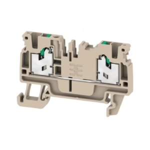
PCB plug-in connector, female plug, 7.62 mm, Number of poles: 2, 180°, PUSH IN with actuator, Tension-clamp connection, Clamping range, max. : 10 mm², Box
Technical Specifications:
| Depth | 47.7 mm |
| Depth (inches) | 1.878 inch |
| Height | 35.05 mm |
| Height (inches) | 1.38 inch |
| Width | 26.4 mm |
| Width (inches) | 1.039 inch |
| Net weight | 22.827 g |
| RoHS Compliance Status | Compliant without exemption |
| REACH SVHC | No SVHC above 0.1 wt% |
| Product family | OMNIMATE Power – series BV/SV 7.62HP |
| Type of connection | Field connection |
| Wire connection method | PUSH IN with actuator Tension-clamp connection |
| Pitch in mm (P) | 7.62 mm |
| Pitch in inches (P) | 0.3 “ |
| Conductor outlet direction | 180° |
| Number of poles | 2 |
| L1 in mm | 15.24 mm |
| L1 in inches | 0.6 “ |
| Number of rows | 2 |
| Pin series quantity | 1 |
| Touch-safe protection acc. to DIN VDE 57 106 | Safe from finger touch |
| Touch-safe protection acc. to DIN VDE 0470 | IP 20 |
| Protection degree | IP20 |
| Volume resistance | 4.50 mΩ |
| Can be coded | Yes |
| Stripping length | 12 mm |
| Stripping length tolerance | min.: -1 mm max.: 1 mm |
| Screwdriver blade | 0.6 x 3.5 |
| Plugging cycles | 25 |
| Plugging force/pole, max. | 12 N |
| Pulling force/pole, max. | 12 N |
| Insulating material | PA GF |
| Colour | black |
| Colour chart (similar) | RAL 9011 |
| Insulating material group | I |
| Comparative Tracking Index (CTI) | ≥ 600 |
| UL 94 flammability rating | V-0 |
| Contact material | Cu-alloy |
| Contact surface | tinned |
| Layer structure of solder connection | 1…3 µm Ni / 4…10 µm Sn |
| Storage temperature, min. | -40 °C |
| Storage temperature, max. | 70 °C |
| Operating temperature, min. | -50 °C |
| Operating temperature, max. | 120 °C |
| Clamping range, min. | 0.5 mm² |
| Clamping range, max. | 10 mm² |
| Wire connection cross section AWG, min. | AWG 24 |
| Wire connection cross section AWG, max. | AWG 8 |
| Solid, min. H05(07) V-U | 0.5 mm² |
| Solid, max. H05(07) V-U | 10 mm² |
| Stranded, min. H07V-R | 1.5 mm² |
| Stranded, max. H07V-R | 6 mm² |
| Flexible, min. H05(07) V-K | 0.5 mm² |
| Flexible, max. H05(07) V-K | 10 mm² |
| w. plastic collar ferrule, DIN 46228 pt 4, min. | 0.5 mm² |
| w. wire end ferrule, DIN 46228 pt 1, min. | 0.5 mm² |
| w. wire end ferrule, DIN 46228 pt 1, max. | 6 mm² |
| Clampable conductor | Cross-section for conductor connection: nominal: 0.5 mm² wire end ferrule: Stripping length: nominal: 14 mm Recommended wire-end ferrule: 0409500000 Cross-section for conductor connection: nominal: 0.75 mm² wire end ferrule: Stripping length: nominal: 14 mm Recommended wire-end ferrule: 9025910000 Cross-section for conductor connection: nominal: 1 mm² wire end ferrule: Stripping length: nominal: 15 mm Recommended wire-end ferrule: 9025930000 Cross-section for conductor connection: nominal: 1.5 mm² wire end ferrule: Stripping length: nominal: 12 mm Recommended wire-end ferrule: 9004060000 Stripping length: nominal: 15 mm Recommended wire-end ferrule: 9019140000 Cross-section for conductor connection: nominal: 2.5 mm² wire end ferrule: Stripping length: nominal: 12 mm Recommended wire-end ferrule: 0186100000 Stripping length: nominal: 14 mm Recommended wire-end ferrule: 9019170000 Cross-section for conductor connection: nominal: 4 mm² wire end ferrule: Stripping length: nominal: 12 mm Recommended wire-end ferrule: 0244100000 Stripping length: nominal: 14 mm Recommended wire-end ferrule: 9019200000 Cross-section for conductor connection: nominal: 6 mm² wire end ferrule: Stripping length: nominal: 12 mm Recommended wire-end ferrule: 0191900000 Stripping length: nominal: 14 mm Recommended wire-end ferrule: 0533500000 Cross-section for conductor connection: nominal: 10 mm² |
| Reference text | The outside diameter of the plastic collar should not be larger than the pitch (P) Length of ferrules is to be chosen depending on the product and the rated voltage. |
| tested acc. to standard | IEC 60664-1 IEC 61984 |
| Rated current, min. number of poles (Tu=20°C) | 46 A |
| Rated current, max. number of poles (Tu=20°C) | 41 A |
| Rated current, min. number of poles (Tu=40°C) | 38 A |
| Rated current, max. number of poles (Tu=40°C) | 37.5 A |
| Rated voltage for surge voltage class / pollution degree II/2 | 600 V |
| Rated voltage for surge voltage class / pollution degree III/2 | 600 V |
| Rated voltage for surge voltage class / pollution degree III/3 | 1,000 V |
| Rated impulse voltage for surge voltage class/ pollution degree II/2 | 4 kV |
| Rated impulse voltage for surge voltage class/ pollution degree III/2 | 6 kV |
| Rated impulse voltage for surge voltage class/ contamination degree III/3 | 6 kV |
| Short-time withstand current resistance | 3 x 1s with 400 A |
| Clearance, min. | 10.36 mm |
| Creepage distance, min. | 11.03 mm |
| Institute (cURus) | CURUS |
| Certificate No. (cURus) | E60693 |
| Rated voltage (Use group B / UL 1059) | 600 V |
| Rated voltage (Use group C / UL 1059) | 600 V |
| Rated voltage (Use group D / UL 1059) | 600 V |
| Rated voltage (Use group E / UL 1059) | 1,000 V |
| Rated current (Use group B / UL 1059) | 35 A |
| Rated current (Use group C / UL 1059) | 35 A |
| Rated current (Use group D / UL 1059) | 35 A |
| Rated current (Use group E / UL 1059) | 35 A |
| Wire cross-section, AWG, min. | AWG 24 |
| Wire cross-section, AWG, max. | AWG 8 |
| Reference to approval values | Specifications are maximum values, details – see approval certificate. |
| Packaging | Box |
| VPE length | 355 mm |
| VPE width | 135 mm |
| VPE height | 59 mm |
| Test Durability of markings | Standard: IEC 61984 section 7.3.2 / 10.08 Taking pattern from IEC 60068-2-70 / 12.95 Test: mark of origin, type identification, pitch, durability Evaluation: available |
| Test Clampable cross section | Standard: DIN EN 60999-1 section 7 and 9.1 / 12.00, DIN EN 60947-1 section 8.2.4.5.1 / 04.08 Conductor type: Type of conductor and conductor cross-section: H05V-U0.5 Type of conductor and conductor cross-section: H05V-K0.5 Type of conductor and conductor cross-section: H07V-K6 Type of conductor and conductor cross-section: H07V-K10 Type of conductor and conductor cross-section: AWG 24/1 Type of conductor and conductor cross-section: AWG 24/19 Type of conductor and conductor cross-section: AWG 8/19 Evaluation: passed |
| Test for damage to and accidental loosening of conductors | Standard: IEC 60999-1 section 9.4 / 11.99 Requirement: 0.2 kg Conductor type: Type of conductor and conductor cross-section: AWG 24/1 Type of conductor and conductor cross-section: AWG 24/19 Evaluation: passed Requirement: 0.3 kg Conductor type: Type of conductor and conductor cross-section: H05V-U0.5 Type of conductor and conductor cross-section: H05V-K0.5 Evaluation: passed Requirement: 1.4 kg Conductor type: Type of conductor and conductor cross-section: H07V-K6 Evaluation: passed Requirement: 2.0 kg Conductor type: Type of conductor and conductor cross-section: H07V-U10 Type of conductor and conductor cross-section: AWG 8/19 Evaluation: passed |
| Pull-out test | Standard: IEC 60999-1 section 9.5 / 11.99 Requirement: ≥10 N Conductor type: Type of conductor and conductor cross-section: AWG 24/1 Type of conductor and conductor cross-section: AWG 24/19 Evaluation: passed Requirement: ≥20 N Conductor type: Type of conductor and conductor cross-section: H05V-U0.5 Type of conductor and conductor cross-section: H05V-K0.5 Evaluation: passed Requirement: ≥80 N Conductor type: Type of conductor and conductor cross-section: H07V-K6 Evaluation: passed Requirement: ≥ 90N Conductor type: Type of conductor and conductor cross-section: H07V-K10 Type of conductor and conductor cross-section: AWG 8/19 Evaluation: passed |
| IPC conformity | Conformity: The products are developed, manufactured and delivered according international recognized standards and norms and comply with the assured properties in the data sheet resp. fulfill decorative properties in accordance with IPC-A-610 “Class 2”. Further claims on the products can be evaluated on request. |
| Notes | Additional variants on request Wire end ferrule with plastic collar to DIN 46228/4 Wire end ferrule without plastic collar to DIN 46228/1 P on drawing = pitch Rated data refer only to the component itself. Clearance and creepage distances to other components are to be designed in accordance with the relevant application standards. In accordance with IEC 61984, OMNIMATE-connectors are connectors without breaking capacity (COC). During designated use, connectors are not allowed to be engaged or disengaged when live or under load Long term storage of the product with average temperature of 50 °C and maximum humidity 70%, 36 months |
Reviews
There are no reviews yet.