
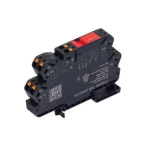
EX signal isolating converter, 1-channel, Ex-input: NAMUR sensor/switch, Safe-output: relay, NC contact
Technical Specifications:
| Depth | 113.6 mm |
| Depth (inches) | 4.472 inch |
| Height | 119.2 mm |
| Height (inches) | 4.693 inch |
| Width | 22.5 mm |
| Width (inches) | 0.886 inch |
| Net weight | 175 g |
| Storage temperature | -20 °C…85 °C |
| Operating temperature | -20 °C…60 °C |
| Humidity | 0…95 % (no condensation) |
| SIL PAPER | SIL certificate |
| SIL in compliance with IEC 61508 | 2 |
| MTBF | 207 a |
| RoHS Compliance Status | Compliant with exemption |
| RoHS Exemption (if applicable/known) | 7a, 7cI |
| REACH SVHC | Lead 7439-92-1 |
| SCIP | 2f6dd957-421a-46db-a0c2-cf1609156924 |
| Mounting position | horizontal or vertical |
| Rail | TS 35 |
| Type of mounting | Snap mounting support rail |
| Input frequency | <20 Hz |
| Input resistance | 1 kΩ |
| NAMUR supply | 8 V DC / 8 mA |
| Output signal in case of wire break | 6.5 mA (in case of wire break) |
| Pulse duration | > 0.1 ms |
| Resistance | RP = 750 Ω / RS = 15kΩ |
| Sensor | NAMUR sensor, according to EN60947-5-6 switch with or without RS, RP |
| Sensor supply | 8 V DC / 8 mA |
| Trigger level high | > 2.1 mA |
| Trigger level low | <1.2 mA |
| Type | intrinsically safe circuit |
| Continuous current | ≤ 2 A AC/DC (safe area, Zone 2 area) |
| Function | Output = input direct or inverse (configurable) |
| Max. switching frequency | 20 Hz |
| Nominal switching voltage | ≤ 250 V AC / 30 V DC (safe area)≤ 32 V AC / 32 V DC (zone 2) |
| Switching capacity | 500 VA / 60 W (safe area) 16 VA / 60 W (zone 2) |
| Type | Relay, 1 NC contact Switching frequency 20 Hz |
| Alarm function | Line interruption at the input Short circuit at input No supply voltage Device error |
| Continuous current | ≤ 0.5 A AC / 0.3 A DC (safe zone) ≤ 0,5 A AC / 1 A DC (zone 2) |
| Nominal switching voltage | ≤ 125 V AC / 110 V DC (safe area)≤ 32 V AC / 32 V DC (zone 2) |
| Power rating | ≤ 62.5 VA / 32 W (safe area)≤ 16 VA / 32 W (Zone 2) |
| Type | Status relay 1 NC (voltage-free) |
| Configuration | With FDT/DTM software Requires configuration adapter 8978580000 CBX200 USB |
| Humidity | 0…95 % (no condensation) |
| Operating altitude | ≤ 2000 m |
| Power consumption | ≤ 1.3 W |
| Protection degree | IP20 |
| Type of connection | Screw connection |
| Voltage supply | 19.2…31.2 V DC |
| EMC standards | EN 61326-1 |
| Insulation voltage | 2.6 kV (input / output) |
| Rated voltage | 300 V |
| Standards | EN 61010-1 |
| Current I0 | 12 mA DC |
| Installation location | Device installed in safe area, zone 2 |
| Marking | II (1) G [Ex ia Ga] IIC/IIB/IIA II (1) D [Ex ia Da] IIIC I (M1) [Ex ia Ma] I |
| Power P0 | 32 mW |
| Voltage U0 | 10.6 V DC |
| Description of the “safe state” | de-energized (relay output) |
| Device type | B |
| Diagnostic test interval | 10 s |
| Tproof | 4 a |
| Total failure rate for safe detected failures (λSD) | 0 FIT |
| Hardware fault tolerance (HFT) | 0 |
| Safety category | SIL 2 |
| Relay lifetime | 100000 times |
| Safe Failure Fraction (SFF) | 90 % |
| Mean Time To Repair (MTTR) | 8 h |
| Total failure rate for safe undetected failures (λSU) | 289 FIT |
| Total failure rate for dangerous detected failures (λDD) | 130 FIT |
| Total failure rate for dangerous undetected failures (λDU) | 46 FIT |
| Probability of outage PFH | 4.66 x 10⁻⁸ h-1 |
| Demand mode | High |
| Demand rate | 1,000 s |
| Demand response time | <10 ms (relay output) |
| Safe Failure Fraction (SFF) | 90 % |
| Average Probability of Failure on Demand (PFDavg) | 2.04 x 10⁻⁴ (Tproof = 1 year) 4.08 x 10⁻⁴ (Tproof = 2 years) 1.02 x 10⁻⁴ (Tproof = 5 years) |
| Type of connection | Screw connection |
| Tightening torque, min. | 0.4 Nm |
| Tightening torque, max. | 0.6 Nm |
| Clamping range, rated connection | 2.5 mm² |
| Clamping range, min. | 0.25 mm² |
| Clamping range, max. | 2.5 mm² |
| Wire connection cross section AWG, min. | AWG 26 |
| Wire connection cross section AWG, max. | AWG 12 |
| Time interval | 3 years |
| Long specification | Ex isolating switch amplifiers for Namur sensors 1-channel isolating switch amplifiers in 22.5 mm width with an external power supply, to transmit and isolate Namur sensor signals from Ex zones 0,1,2 into the safe zone. On the output side there is a potential-free relay contact with opening function and an alarm contact (“a” contact) for status/error messages. The component can be configured using standard FDT/DTM software. Add-on housing for TS35 DIN rail installation Dimensions: L/W/H 119.2/ 22.5/ 113.6screw connection/ nominal cross-section 2.5 mm2Protection degree: IP20 Input NAMUR sensor according to EN 60947 8 VDC / 8 mA sensor power supply 0 to 5 kHz input frequency wire-break detectionoutput Relay 1 NC contact 250 VAC / 30 VDC @ 2A safe zone 32 VAC @ 0.5 A/ 32 VDC @ 1 A zone 2Alarm output relay 1 NO contact 250 VAC / 30 VDC @ 2A safe zone 32 VAC @ 0.5 A/ 32 VDC @ 1 A zone 2 Auxiliary power 19 to 31.2 VDCPower loss approx. 1.8 WAmbient temperature range -20 °C to +60 °C Secure isolation EN 61010, 3-way isolation up to 2.6 kV AC/DC of all circuits against each otherWorking voltage 300 V AC/DC at overvoltage category II and pollution degree 2 Approvals cULus, ATEX IECEX, FM ATEX marking II 3 G ExnA nC IIC T4 ATEX characteristic data U0 = 10, 6 V DC I0 = 12 mA DC P0 = 32 W Type ACT20X-HDI-SDO-RNC-S |
| Short specification | Ex isolating switch amplifiers for Namur sensors1-channel isolating switch amplifiers in 22.5 mm width with an external power supply,to transmit and isolate Namur sensor signals from Ex zones 0,1,2 into the safe zone. On the output side there is a potential-free relay contact with opening function and an alarm contact (“a” contact)for status/error messages.The component can be configured using standard FDT/DTM software. |


Reviews
There are no reviews yet.