
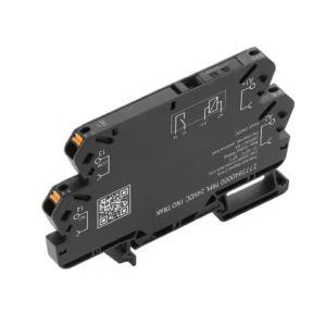
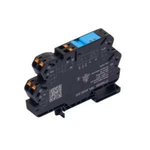
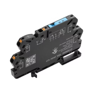
EX signal isolating converter, Safe-input: relay, Ex-output: Opto module, High-current, 1-channel, Output current : max. 60 mA
Technical Specifications:
| Depth | 113.6 mm |
| Depth (inches) | 4.472 inch |
| Height | 127.1 mm |
| Height (inches) | 5.004 inch |
| Width | 22.5 mm |
| Width (inches) | 0.886 inch |
| Net weight | 170 g |
| Storage temperature | -20 °C…85 °C |
| Operating temperature | -20 °C…60 °C |
| Humidity | 0…95 % (no condensation) |
| SIL in compliance with IEC 61508 | 2 |
| MTBF | 175 a |
| SFF | 91 % |
| RoHS Compliance Status | Compliant with exemption |
| RoHS Exemption (if applicable/known) | 7a, 7cI |
| REACH SVHC | Lead 7439-92-1 |
| SCIP | 2f6dd957-421a-46db-a0c2-cf1609156924 |
| Mounting position | horizontal or vertical |
| Rail | TS 35 |
| Type of mounting | Snap mounting support rail |
| Input resistance, voltage | 3.5 kΩ |
| Input voltage | ≤ 28 V DC Trigger level low: ≤ 2.0 V DC (NPN), ≤ 8.0 V DC (PNP) Trigger level high: ≥ 4.0 V DC (NPN), ≥ 10.0 V DC (PNP) |
| Number of inputs | 1 |
| Sensor | NAMUR sensor, according to EN60947-5-6 |
| Type | NPN, PNP transistor, switching signal [input safe-side valve component] |
| Output current | max. 60 mA |
| Output values | depending on terminal assignment |
| Residual ripple (current loop) | <40 mVeff |
| Type | intrinsically safe circuit digital, output = input direct or inverse (configurable) |
| Max. switching frequency | 20 Hz |
| Alarm function | No supply voltage Device error |
| Continuous current | ≤ 0.5 A AC / 0.3 A DC (safe zone) ≤ 0,5 A AC / 1 A DC (zone 2) |
| Nominal switching voltage | ≤ 125 V AC / 110 V DC (safe area)≤ 32 V AC / 32 V DC (zone 2) |
| Power rating | ≤ 62.5 VA / 32 W (safe area)≤ 16 VA / 32 W (Zone 2) |
| Type | Status relay 1 NC (voltage-free) |
| Configuration | With FDT/DTM software Requires configuration adapter 8978580000 CBX200 USB |
| Humidity | 0…95 % (no condensation) |
| Operating altitude | ≤ 2000 m |
| Power consumption | ≤ 1.9 W |
| Protection degree | IP20 |
| Step response time | 10 ms |
| Type of connection | PUSH IN |
| Voltage supply | 19.2…31.2 V DC |
| EMC standards | EN 61326-1 |
| Insulation voltage | 2.6 kV (input / output) |
| Rated voltage | 300 V |
| Standards | EN 61010-1 |
| Current I0 | ≤ 135 mA |
| Installation location | Device installed in safe area, zone 2 |
| Marking | II (1) G [Ex ia Ga] IIC/IIB/IIA II (1) D [Ex ia Da] IIIC I (M1) [Ex ia Ma] I |
| Power P0 | ≤ 0.77 W |
| Voltage U0 | 28 V DC |
| Description of the “safe state” | de-energized (relay output) |
| Device type | B |
| Diagnostic test interval | 10 s |
| Tproof | 4 a |
| Total failure rate for safe detected failures (λSD) | 0 FIT |
| Hardware fault tolerance (HFT) | 0 |
| Safety category | SIL 2 |
| Safe Failure Fraction (SFF) | 91 % |
| Mean Time To Repair (MTTR) | 24 h |
| Total failure rate for safe undetected failures (λSU) | 480 FIT |
| Total failure rate for dangerous detected failures (λDD) | 61 FIT |
| Total failure rate for dangerous undetected failures (λDU) | 46 FIT |
| Probability of outage PFH | 4.6 x 10⁻⁸ h-1 |
| Demand mode | High |
| Demand rate | 1,000 s |
| Demand response time | <10 ms (opto output) |
| Average Probability of Failure on Demand (PFDavg) | 2.92 x 10⁻⁴ (Tproof = 1 year) 4.84 x 10⁻⁴ (Tproof = 2 year) 1.06 x 10⁻⁴ (Tproof = 5 year) |
| Type of connection | PUSH IN |
| Wire connection cross section AWG, min. | AWG 26 |
| Wire connection cross section AWG, max. | AWG 14 |
| Wire cross-section, solid, min. | 0.2 mm² |
| Wire cross-section, solid, max. | 2.5 mm² |
| Wire connection cross section, finely stranded, min. | 0.2 mm² |
| Wire connection cross section, finely stranded, max. | 2.5 mm² |
| Wire connection cross-section, finely stranded with wire-end ferrules DIN 46228/4, min. | 0.2 mm² |
| Wire connection cross-section, finely stranded with wire-end ferrules DIN 46228/4, max. | 2.5 mm² |
| Time interval | 3 years |

Reviews
There are no reviews yet.