
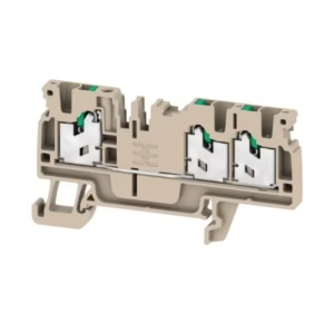
Printed circuit board terminals, 5.00 mm, Number of poles: 8, 135°, Solder pin length (l): 3.5 mm, black, PUSH IN with actuator, Clamping range, max. : 1.5 mm², Tape
Technical Specifications:
| Depth | 12.7 mm |
| Depth (inches) | 0.5 inch |
| Height | 16.4 mm |
| Height (inches) | 0.646 inch |
| Height of lowest version | 12.9 mm |
| Width | 39.2 mm |
| Width (inches) | 1.543 inch |
| Net weight | 9.026 g |
| Continuous operating temp., max. | 120 °C |
| RoHS Compliance Status | Compliant without exemption |
| REACH SVHC | No SVHC above 0.1 wt% |
| Product family | OMNIMATE Signal – series LSF |
| Wire connection method | PUSH IN with actuator |
| Mounting onto the PCB | THT/THR solder connection |
| Conductor outlet direction | 135° |
| Pitch in mm (P) | 5 mm |
| Pitch in inches (P) | 0.197 “ |
| Number of poles | 8 |
| Pin series quantity | 1 |
| Fitted by customer | No |
| Number of rows | 1 |
| Solder pin length (l) | 3.5 mm |
| Solder pin length tolerance | +0.1 / -0.3 mm |
| Solder pin dimensions | 0.35 x 0.8 mm |
| Solder pin dimensions = d tolerance | 0 / -0.1 mm |
| Solder eyelet hole diameter (D) | 1.1 mm |
| Solder eyelet hole diameter tolerance (D) | + 0,1 mm |
| Number of solder pins per pole | 2 |
| Stripping length | 8 mm |
| L1 in mm | 35 mm |
| L1 in inches | 1.378 “ |
| Touch-safe protection acc. to DIN VDE 0470 | IP 20 |
| Touch-safe protection acc. to DIN VDE 57 106 | Safe from finger touch |
| Protection degree | IP20 |
| Volume resistance | 1.60 mΩ |
| Insulating material | LCP GF |
| Colour | black |
| Colour chart (similar) | RAL 9011 |
| Insulating material group | IIIa |
| Comparative Tracking Index (CTI) | ≥ 175 |
| Moisture Level (MSL) | 1 |
| UL 94 flammability rating | V-0 |
| Contact material | Cu-alloy |
| Layer structure of solder connection | 4…6 µm Sn matt |
| Storage temperature, min. | -40 °C |
| Storage temperature, max. | 70 °C |
| Operating temperature, min. | -50 °C |
| Operating temperature, max. | 120 °C |
| Temperature range, installation, min. | -30 °C |
| Temperature range, installation, max. | 120 °C |
| Clamping range, min. | 0.13 mm² |
| Clamping range, max. | 1.5 mm² |
| Wire connection cross section AWG, min. | AWG 28 |
| Wire connection cross section AWG, max. | AWG 14 |
| Solid, min. H05(07) V-U | 0.2 mm² |
| Solid, max. H05(07) V-U | 1.5 mm² |
| Flexible, min. H05(07) V-K | 0.2 mm² |
| Flexible, max. H05(07) V-K | 1.5 mm² |
| w. plastic collar ferrule, DIN 46228 pt 4, min. | 0.25 mm² |
| w. plastic collar ferrule, DIN 46228 pt 4, max. | 0.75 mm² |
| w. wire end ferrule, DIN 46228 pt 1, min. | 0.25 mm² |
| w. wire end ferrule, DIN 46228 pt 1, max. | 1.5 mm² |
| Clampable conductor | Cross-section for conductor connection: Type: fine-wired nominal: 0.25 mm² wire end ferrule: Stripping length: nominal: 10 mm Recommended wire-end ferrule: 9025760000 Cross-section for conductor connection: Type: fine-wired nominal: 0.34 mm² wire end ferrule: Stripping length: nominal: 10 mm Recommended wire-end ferrule: 9025770000 Cross-section for conductor connection: Type: fine-wired nominal: 0.5 mm² wire end ferrule: Stripping length: nominal: 10 mm Recommended wire-end ferrule: 0690700000 Cross-section for conductor connection: Type: fine-wired nominal: 0.75 mm² wire end ferrule: Stripping length: nominal: 10 mm Recommended wire-end ferrule: 9021040000 |
| Reference text | Length of ferrules is to be chosen depending on the product and the rated voltage. The outside diameter of the plastic collar should not be larger than the pitch (P) |
| tested acc. to standard | IEC 60664-1 IEC 61984 |
| Rated current, min. number of poles (Tu=20°C) | 17.5 A |
| Rated current, max. number of poles (Tu=20°C) | 17.5 A |
| Rated current, min. number of poles (Tu=40°C) | 17.5 A |
| Rated current, max. number of poles (Tu=40°C) | 15 A |
| Rated voltage for surge voltage class / pollution degree II/2 | 500 V |
| Rated voltage for surge voltage class / pollution degree III/2 | 320 V |
| Rated voltage for surge voltage class / pollution degree III/3 | 250 V |
| Rated impulse voltage for surge voltage class/ pollution degree II/2 | 4 kV |
| Rated impulse voltage for surge voltage class/ pollution degree III/2 | 4 kV |
| Rated impulse voltage for surge voltage class/ contamination degree III/3 | 4 kV |
| Short-time withstand current resistance | 3 x 1s with 80 A |
| Institute (CSA) | CSA |
| Certificate No. (CSA) | 200039-1664286 |
| Rated voltage (Use group B / CSA) | 300 V |
| Rated voltage (Use group D / CSA) | 300 V |
| Rated current (Use group B / CSA) | 10 A |
| Rated current (Use group D / CSA) | 10 A |
| Wire cross-section, AWG, min. | AWG 28 |
| Wire cross-section, AWG, max. | AWG 14 |
| Reference to approval values | Specifications are maximum values, details – see approval certificate. |
| Institute (cURus) | CURUS |
| Certificate No. (cURus) | E60693 |
| Rated voltage (Use group B / UL 1059) | 300 V |
| Rated voltage (Use group D / UL 1059) | 300 V |
| Rated current (Use group B / UL 1059) | 12 A |
| Rated current (Use group D / UL 1059) | 10 A |
| Wire cross-section, AWG, min. | AWG 28 |
| Wire cross-section, AWG, max. | AWG 14 |
| Reference to approval values | Specifications are maximum values, details – see approval certificate. |
| ESD Level packaging | static dissipative |
| Packaging | Tape |
| VPE length | 343 mm |
| VPE width | 339 mm |
| VPE height | 89 mm |
| Tape depth (T2) | 17.7 mm |
| Tape width (W) | 56 mm |
| Tape pocket depth (K0) | 17.2 mm |
| Tape pocket height (A0) | 13 mm |
| Tape pocket width (B0) | 43 mm |
| Tape pocket separation (P1) | 20 mm |
| Tape hole separation (E) | 1.75 mm |
| Tape pocket separation (F) | 26.2 mm |
| Tape reel diameter ∅ (A) | 330 mm |
| Surface resistance | Rs = 109 – 1012 Ω |
| Test Durability of markings | Standard: DIN EN 60512-1-1 / 01.03 Test: mark of origin, type identification, pitch, approval marking UL, durability Evaluation: available |
| Test Clampable cross section | Standard: DIN EN 60999-1 section 7 and 9.1 / 12.00, DIN EN 60947-1 section 8.2.4.5.1 / 12.02 Conductor type: Type of conductor and conductor cross-section: solid 0.14 mm² Type of conductor and conductor cross-section: stranded 0.14 mm² Type of conductor and conductor cross-section: solid 1.5 mm² Type of conductor and conductor cross-section: stranded 1.5 mm² Type of conductor and conductor cross-section: AWG 24/1 Type of conductor and conductor cross-section: AWG 26/19 Type of conductor and conductor cross-section: AWG 16/1 Type of conductor and conductor cross-section: AWG 16/19 Evaluation: passed |
| Test for damage to and accidental loosening of conductors | Standard: DIN EN 60999-1 section 9.4 / 12.00 Requirement: 0.2 kg Conductor type: Type of conductor and conductor cross-section: AWG 24/1 Type of conductor and conductor cross-section: AWG 24/19 Requirement: 0.3 kg Conductor type: Type of conductor and conductor cross-section: stranded 0.25 mm² Type of conductor and conductor cross-section: solid 0.5 mm² Evaluation: passed Requirement: 0.4 kg Conductor type: Type of conductor and conductor cross-section: solid 1.5 mm² Type of conductor and conductor cross-section: stranded 1.5 mm² Type of conductor and conductor cross-section: AWG 16/1 Type of conductor and conductor cross-section: AWG 16/19 Evaluation: passed |
| Pull-out test | Standard: DIN EN 60999-1 section 9.5 / 12.00 Requirement: ≥10 N Conductor type: Type of conductor and conductor cross-section: AWG 24/1 Type of conductor and conductor cross-section: AWG 24/19 Evaluation: passed Requirement: ≥20 N Conductor type: Type of conductor and conductor cross-section: stranded 0.25 mm² Type of conductor and conductor cross-section: H05V-K0.5 Evaluation: passed Requirement: ≥40 N Conductor type: Type of conductor and conductor cross-section: H07V-U1.5 Type of conductor and conductor cross-section: H07V-K1.5 Type of conductor and conductor cross-section: AWG 16/1 Type of conductor and conductor cross-section: AWG 16/19 Evaluation: passed |
| IPC conformity | Conformity: The products are developed, manufactured and delivered according international recognized standards and norms and comply with the assured properties in the data sheet resp. fulfill decorative properties in accordance with IPC-A-610 “Class 2”. Further claims on the products can be evaluated on request. |
| Notes | Additional push button colours on request Operating force of slider max. 40 N Rated current related to rated cross-section & min. No. of poles. Wire end ferrule with plastic collar to DIN 46228/4 Wire end ferrule without plastic collar to DIN 46228/1 P on drawing = pitch Rated data refer only to the component itself. Clearance and creepage distances to other components are to be designed in accordance with the relevant application standards. Crimping shape “A” for wire end ferrules with PZ 6/5 crimping tool recommended. Long term storage of the product with average temperature of 50 °C and maximum humidity 70%, 36 months |
Reviews
There are no reviews yet.